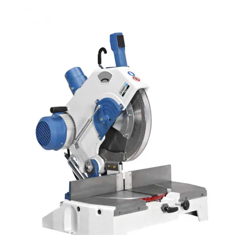
T 50 350
Cast-iron base and head, belt drive and induction motor. Table adjustment allows standard mitre cuts; stop positions make repetition easier.
Technical source: OMGA · T 50 350 ↗

OMGA / MITRE SAWS FOR WOOD AND ALUMINIUM
OMGA mitre saws: T 50 350 for mitre cuts in the plane of the table and T 53 370 with head tilt as well. For wood or aluminium, we match the machine version, saw blade and required accessories.
Explore the options ↓ Official page ↗
TWO MODELS
Cast-iron base and head, belt drive and induction motor. Table adjustment allows standard mitre cuts; stop positions make repetition easier.
Technical source: OMGA · T 50 350 ↗
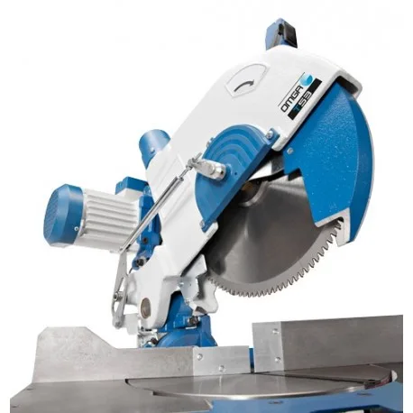
In addition to table rotation, it allows head tilt up to 45°. For angled cuts and compound angles where rotation in one plane is not enough.
Technical source: OMGA · T 53 370 ↗
DIFFERENT CUTTING PLANES
The blade cuts the profile perpendicular to its length. The workpiece has a prepared reference and suitable clamping.
T 50 350 and T 53 370.By rotating, you change the angle between the cut and the longitudinal edge of the profile. A typical example is a 45-degree frame joint.
T 50 350 and T 53 370.On the T 53, you also tilt the head. The sketch switches to a front view so that the second cutting plane is visible. With an additional table rotation, you get a compound cut.
Head tilt: T 53 370.TECHNICAL DATA
| Blade diameter / bore | 350 / 30 mm |
|---|---|
| Motor / speed | 2.2 kW / 3000 min⁻¹ |
| Extraction | Ø 80 mm |
| Cut 90° · width × height | 130 × 110 mm OR 173 × 90 mm |
| Cut 45° · width × height | 92 × 110 mm OR 105 × 90 mm |
| Blade diameter / bore | 370 / 30 mm |
|---|---|
| Motor | Approx. 3 kW · website 2.9; brochure 3.0 kW |
| Speed / extraction | 3000 min⁻¹ / Ø 80 mm |
| Cut 90° · width × height | 173 × 110 mm |
| Cut 45° · width × height | 105 × 110 mm |
| Head tilt 45° for a right-angle cut | 160 × 50 mm |
Width and height are linked: the maximum individual values must not be combined at will. For compound angles, we check the cutting diagram and your profile. T 53 power and the final version are confirmed in the offer.
Technical source: OMGA · T 50 350 ↗
Technical source: OMGA · T 53 370 ↗
SETTING AND CLAMPING
The manufacturer states positive positions for 90°, 45°, 30°, 22°30′, 15° and 10° to both sides, and manual locking of intermediate angles. The available cutting range changes with the angle.
Measuring tables, fold-away stops and suitable supports reduce repeated manual measuring. A long workpiece needs a stable supported infeed and outfeed path.
We select horizontal or vertical clamps according to the profile and the working method. They are part of the agreed equipment; a photo of a richer version does not define the standard supply.
Oil-pneumatic head descent, two-hand operation, pneumatic clamping and a base are features of the OP version in the brochure. We do not present the basic manual model as such a version.
LENGTH FROM PROGRAM
When lengths are repeated, the NC stop can take over setting the length reference. The operator still prepares the material, angle and clamping according to the configuration.
OMGA shows the T 50 350 combination or the OP version with the FP system. The combination requires matched tables, mechanical and control components; it is not an automatic add-on to every existing saw.
Learn about NC positioning ↗CATALOGUE
Manual and OP versions, accessories, angle settings and cutting diagrams.
Official PDF · 3 pages · 1.6 MBCHOICE FOR YOUR PROFILE
Send the cross-section, wall thickness and required angles. For T 50 or T 53, we check the dedicated suitable version, blade, clamping, lubrication and chip removal. Published data for wood are not automatically transferred to aluminium. OMGA also has other specially equipped solutions for aluminium.
When the product, in addition to the angle in the table plane, also requires a bevel cut through the cross-section. For a standard frame with a straight profile, the requirement is different from that for a compound spatial joint.
No. FP sets the length position. Angle setting and the cutting cycle are features of the saw and the agreed combination.
Profile cross-section, material, angles, lengths, tolerance requirements and approximate quantity. For decorative profiles, a drawing of their position during cutting also helps.
EQUIPMENT SELECTION
Specify the material, cross-section, input and final lengths, angles and approximate quantity. Add a description of the current working method. This allows us to determine the right saw, clamping, feed and software options.
Send enquiry ↗The form keeps the source page. The version, accessories and price are determined in an individual offer.