
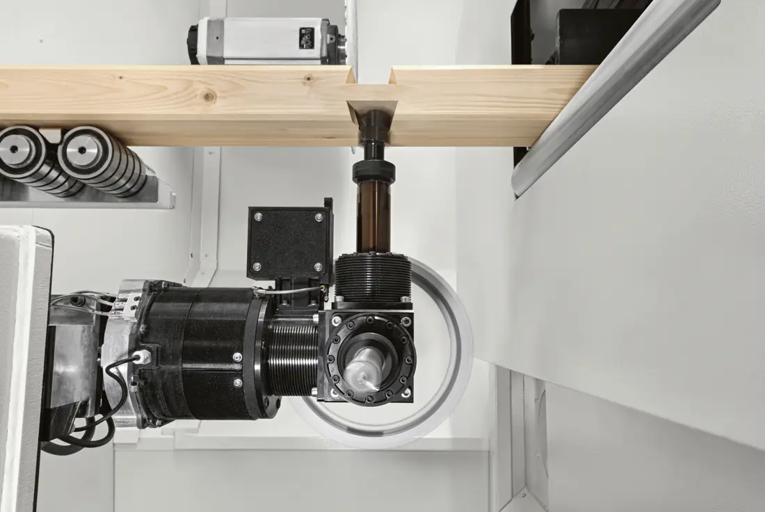
Structural elements
Straight beams, roof elements and components of timber walls. Cross-section and length are crucial when feeding through the machine.
Oikos XS ↓SCM / CNC MACHINES FOR TIMBER CONSTRUCTION
CNC machines for structural timber, large CLT panels and glued beams. Learn about machining, sanding and software preparation, and choose the technology according to the geometry and size of the element.

THREE DIFFERENT TASKS
Straight beams, roof elements and components of timber walls. Cross-section and length are crucial when feeding through the machine.
Oikos XS ↓CLT walls and ceilings with openings, grooves and joints. Head access, clamping and the full panel surface are important.
Area and sanding ↓Large straight or curved glued elements require a different arrangement of supports and machining space.
Area GL ↓SELECTED SCM SYSTEMS

SELECTED TECHNOLOGY
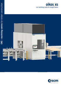
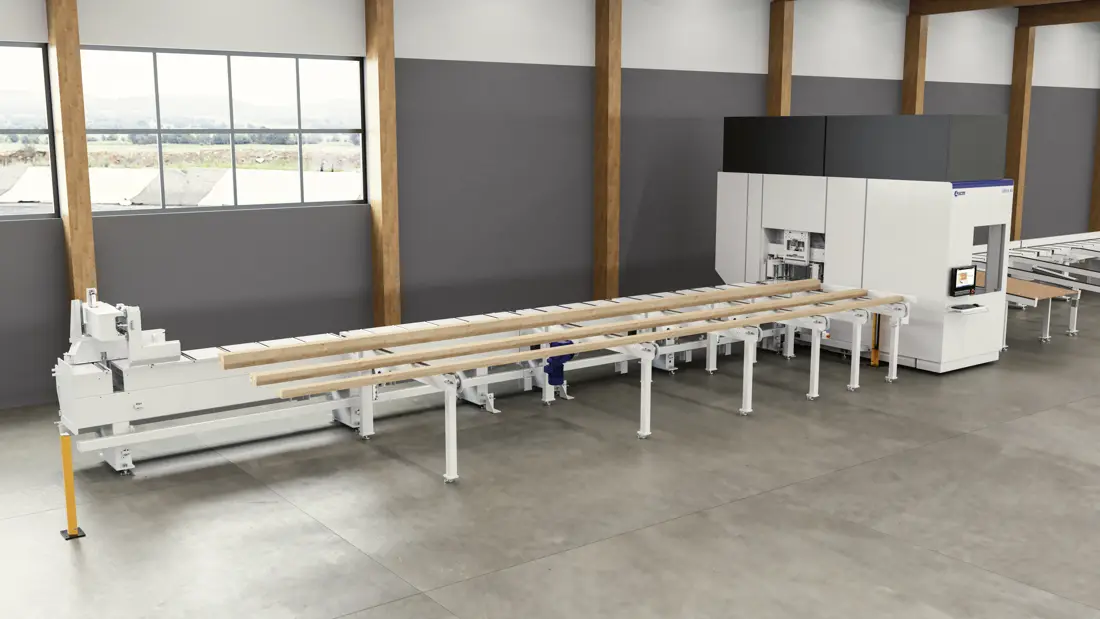
A machining centre for solid and glued flat structural elements. The feed system guides the element through the machining area; the Revolver five-axis unit is available in both versions, and the additional Flex-5 head on the XS 650.
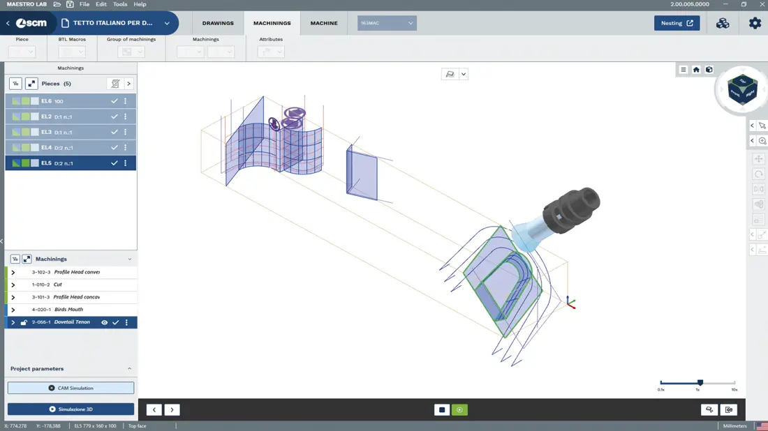
Maestro lab beam&wall supports operation preparation, while Maestro active beam&wall provides on-machine control. The choice of version depends on cross-sections, lengths and required joints.

SELECTED TECHNOLOGY
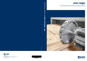
Five-axis gantry centre for CLT panels and large structural elements. Operations include opening cut-outs, trimming and joint making on an already manufactured panel.
A large working area is useful only if clamping, tool access and handling of the element are properly arranged. The beam&wall program supports preparation and simulation; element layout is adapted to the actual execution.


LARGE GLUED ELEMENTS
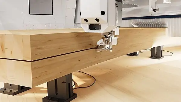
Five-axis centre for machining straight or curved glued beams. Here too we are talking about machining an already manufactured glued element; gluing and pressing are separate processes.
Different supports allow adaptation to the geometry. Maestro lab beam&wall and Maestro active beam&wall connect programming and machining execution.


CALIBRATING AND SANDING CLT
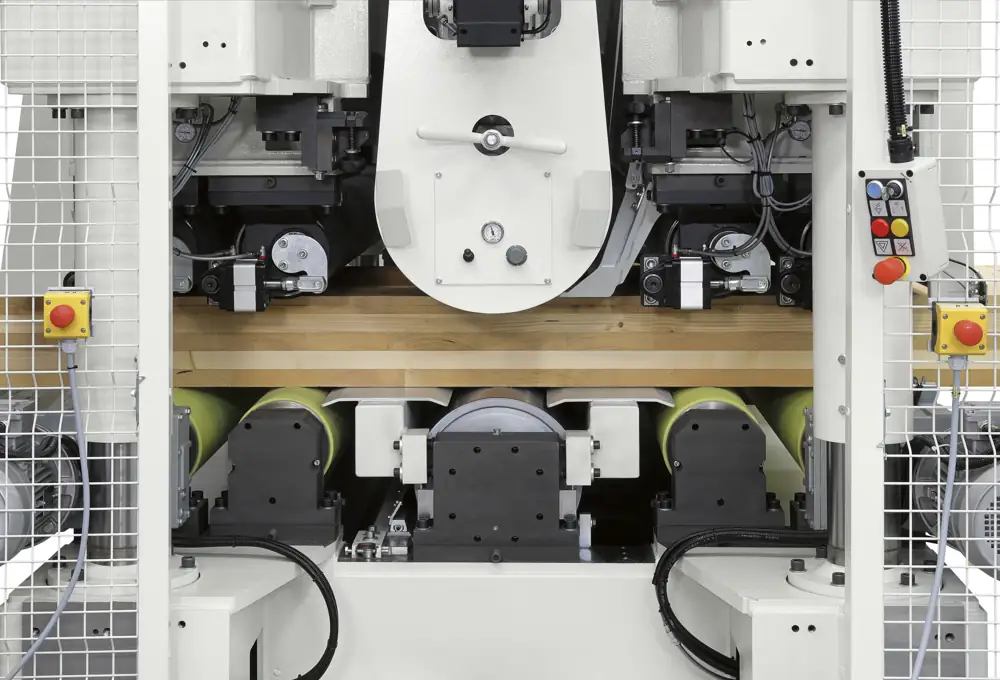
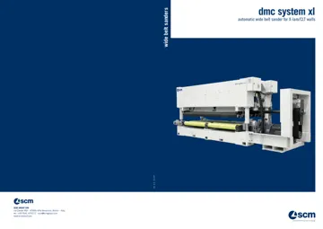
Wide-belt system for surface processing of cross-laminated timber panels. Calibrating is intended to achieve the required thickness, while sanding prepares the surface. The place of this operation in production is determined according to panel manufacture and the requirements of the final product.
The modular design allows combinations of units for the top and bottom side. The version may include a calibration roller, segmented EPICS sanding shoe and a cross sanding unit. These are selected according to the required material removal, surface and panel make-up.
The minimum workpiece thickness and permitted machining method depend on the machine configuration. The catalogue and portal data variations are checked for the selected configuration.
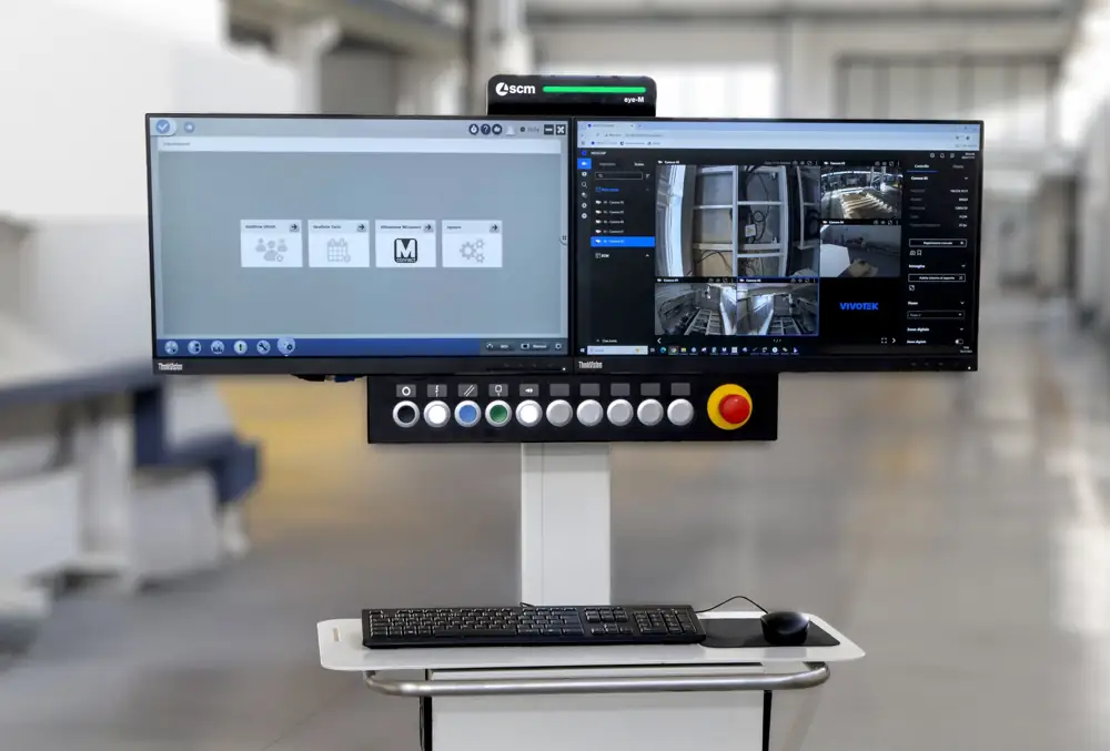
Through the eye-M console, the operator sets the machining parameters and controls the sanding process. This interface is intended for sanding; preparation of structural machining on AREA and OIKOS CNC centres uses the beam&wall family.
The width of DMC system XL is 3,700 mm. A larger working area of the CNC centre does not therefore mean that every panel can also be machined on this sanding machine. Element dimensions, operation sequence, feed and handling must be coordinated.
MAESTRO / BEAM & WALL
Wooden structure design, preparation of machining and machine control are connected tasks. The software helps transfer data between them, while the person defines the requirements and checks the preparation.

PREPARATION / OFFICE OR CONSOLE
From the structural design data it prepares machining for AREA and OIKOS CNC centres. It does not replace structural calculations or building design.

EXECUTION / ON THE MACHINE
The operator interface connects prepared programs with the operator’s day-to-day work. The clear console makes it easier to choose the next job and monitor production.
EN ELEMENT / FROM DATA TO MACHINE
BTL/BTLX export transfers the geometry and the description of the machining operations. The preparer checks whether the elements and joints have been read correctly.
Result: an element with machining operations for program preparation.
When you receive a modified element from the design software, prepare and check the machining operations again. Saved strategies are the starting point, so every detail does not need to be prepared again at the machine console. We select the software and training according to your products and work organisation.
For beams, we also deal with the longitudinal distribution of pieces from raw beams. For panels, a two-dimensional layout is important. The point at which optimisation takes place in CAD/CAM preparation or in the control program depends on the generation and configuration used; we verify it on the actual export of your project.
Simulation is part of program verification and does not replace safety procedures on the machine. Licences for office or console preparation, connectivity, tools and optimisation options are determined for the selected machine.
The AREA catalogue and the presentation video below also show the previous generation of Maestro beam&wall. They are intended to help understand the workflow; the interface appearance and functions differ between versions.
VIDEO / SCM
Selected public SCM clips from Partners material. The YouTube player loads after you make your selection.
Display of feed and machining of structural timber.
Open on YouTube ↗Display of the new centre for straight and curved glued elements.
Open on YouTube ↗Public display of the principle of program preparation; the interface appearance depends on the generation.
Open on YouTube ↗Grinding large surfaces as a separate process in production.
Open on YouTube ↗DOWNLOAD MATERIAL

A more detailed presentation of the basic version. For XS 650, use the dedicated material.


Portal centre program. For the newer Area GL, we also use the current model data presented above.

Calibration and sanding of CLT, upper and lower units, Maestro active sand control and technical data. Edition 05/2024 · English · PDF, 1,5 MB.
The catalogues in English present the manufacturer's programme. Equipment, dimensions and software options depend on the selected version; the specific configuration is confirmed with the offer.
ARHAR / EQUIPMENT SELECTION
Specify the type of element, maximum dimensions, an example joint and the expected quantity. For larger elements, we also include transport infeed, feed, unloading and subsequent machining operations.
The enquiry retains the source page information.